


MCO Home - Fan Coil Thermostat 4 pipe MCOEMH8-FC4

Descriere
Informații despre produs "MCO Home -Fan Coil Thermostat 4 pipe"
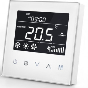
Termostatul MCOEMH8-FC4 este un dispozitiv pentru controlul temperaturii în cameră, echipat cu tehnologie wireless Z-Wave. Este destinat controlului central al unei bobine ventilatoare cu 4 țevi, care influențează clima camerei prin încălzire, răcire, umidificare și dezumidificare. Dispozitivul poate citi temperatura camerei și ora locală și poate controla automat viteza ventilatorului pe baza diferenței de temperatură.
Termostatul de perete MCOEMH8-FC4 necesită o instalație statică cu alimentare la rețea. Datorită design-ului său modern, cu panou capacitiv din sticlă, este deosebit de potrivit pentru instalarea vizibilă în zonele de locuit.
Cu termostatele de sticlă proiectate modern de MCO puteți controla diferite sisteme de încălzire și răcire - de ex. cablu de incalzire, film de incalzire, supapa de apa, supapa electrica, cazan, bobina ventilator, controler de energie solara, pompa de caldura, sistem de ventilatie etc,
Caracteristici:
Controlul central al bobinei ventilatorului cu 4 țevi
Panoul din sticlă din aluminiu (alb) cu butoane capacitive
Afișaj clar, cu informații de control de bază
Modurile de răcire, încălzire și ventilație
Sistem inteligent de pornire / oprire a ventilatorului cu 3 trepte și supapă electrică
Spațiu montat în cutie de joncțiune de 86x86mm
Tehnologia fără fir: Z-Wave Plus
Cod Produs: MCOEMH8-FC4
.
EN
Product Description
MCOHome Fan Coil Thermostat is a Z-Wave enabled device for indoor temperature control. It is mainly applied to a 4-pipe Fan coil system. It can read room temperature and local time, and automatically control fan speed based on the temperature difference. The device is of high reliability and practicability. This product can be included and operated in any Z-Wave network with other Z-Wave certified devices from any other manufacturers.
Prepare for Installation / Reset
Please read the user manual before installing the product.
In order to include (add) a Z-Wave device to a network it must be in factory default state. Please make sure to reset the device into factory default. You can do this by performing an Exclusion operation as described below in the manual. Every Z-Wave controller is able to perform this operation however it is recommended to use the primary controller of the previous network to make sure the very device is excluded properly from this network.
Safety Warning for Mains Powered Devices
ATTENTION: only authorized technicians under consideration of the country-specific installation guidelines/norms may do works with mains power. Prior to the assembly of the product, the voltage network has to be switched off and ensured against re-switching.
Installation
Location:
Thermostat is suggested to be installed indoor, a place with around 1.5m height above the floor where represents the average room temperature. It should be away from direct sunlight, any cover, or any heat source, to avoid false signal for temperature control.
CAUTION: Cut off power supply at circuit breaker or fuse before installation to avoid fire, shock or death!

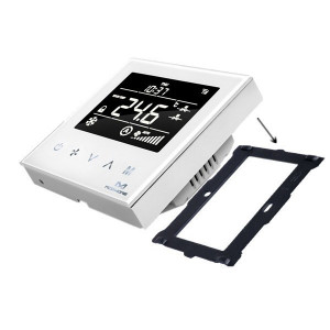
Step 1: Remove the steel frame from the device, and secure it onto the junction box with two screws.
Step 2: Insert all wires into the right terminals and tighten screws. The wiring diagram is shown below.
Step 3: Attach the wired device on A points of the steel frame as shown first, and then push the whole device into junction box.
Step 4: Confirm the device is well mounted, power on and it is ready to operate.

Note: CO--Cool Valve Open; CC--Cool Valve Close; HO--Heat Valve Open; HC--Heat Valve Close
On/Off Setting
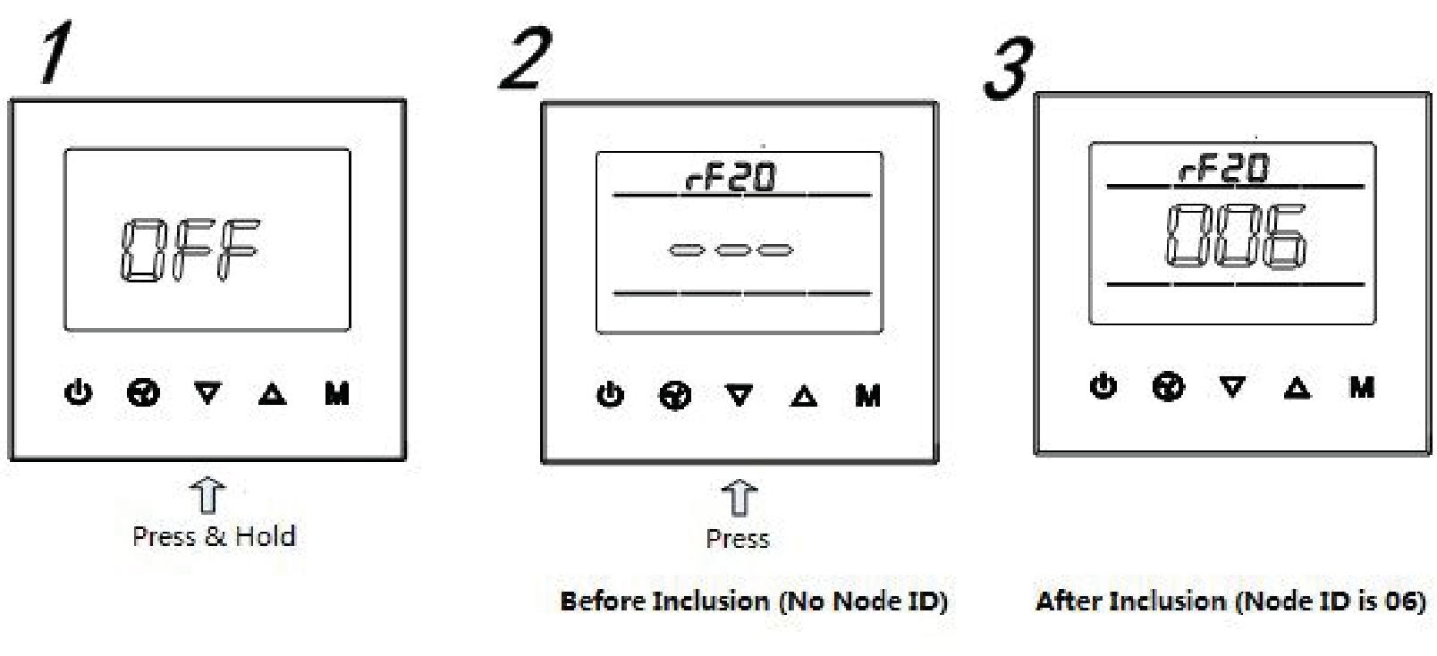
When power on, thermostat will display OFF - press power button to enter working interface. When normal working, press power button to turn off the device, OFF displays and all outputs are off.
Safety Warning for Mains Powered Devices
ATTENTION: only authorized technicians under consideration of the country-specific installation guidelines/norms may do works with mains power. Prior to the assembly of the product, the voltage network has to be switched off and ensured against re-switching.
Installation
Location:
Thermostat is suggested to be installed indoor, a place with around 1.5m height above the floor where represents the average room temperature. It should be away from direct sunlight, any cover, or any heat source, to avoid false signal for temperature control.
CAUTION: Cut off power supply at circuit breaker or fuse before installation to avoid fire, shock or death!
- Step 1: Remove the steel frame from the device, and secure it onto the junction box with two screws.
- Step 2: Insert all wires into the right terminals and tighten screws. The wiring diagram is shown below.
- Step 3: Attach the wired device on A points of the steel frame as shown first, and then push the whole device into junction box.
- Step 4: Confirm the device is well mounted, power on and it is ready to operate.
Note: CO--Cool Valve Open; CC--Cool Valve Close; HO--Heat Valve Open; HC--Heat Valve Close
On/Off Setting
When power on, thermostat will display OFF - press power button to enter working interface. When normal working, press power button to turn off the device, OFF displays and all outputs are off.
Inclusion/Exclusion
On factory default the device does not belong to any Z-Wave network. The device needs to be added to an existing wireless network to communicate with the devices of this network. This process is called Inclusion.
Devices can also be removed from a network. This process is called Exclusion. Both processes are initiated by the primary controller of the Z-Wave network. This controller is turned into exclusion respective inclusion mode. Inclusion and Exclusion is then performed doing a special manual action right on the device.
Inclusion
Including and Excluding of Z-Wave network
Under the shutdown state, press and hold down arrow to enter interface for inclusion or exclusion of Z-Wave network. Before device included into network, (- - -) will display on the screen. Then press down arrow once, device will enter learning mode to get a node ID. If inclusion is success, a node ID will display on the screen in a few seconds. A node ID can always inform us whether the device is in the network or not. Note: Follow the same steps to exclude the device from the network. After inclusion, turn off the device and then turn it on. Now the device is ready to be operated by controller/ gateway in Z-Wave network.
Exclusion
Including and Excluding of Z-Wave network
Under the shutdown state, press and hold down arrow to enter interface for inclusion or exclusion of Z-Wave network. Before device included into network, (- - -) will display on the screen. Then press down arrow once, device will enter learning mode to get a node ID. If inclusion is success, a node ID will display on the screen in a few seconds. A node ID can always inform us whether the device is in the network or not. Note: Follow the same steps to exclude the device from the network. After inclusion, turn off the device and then turn it on. Now the device is ready to be operated by controller/ gateway in Z-Wave network.
Product Usage

Local Time Setting
Press and hold M to enter local time setting. Touch M to switch among Week, Hour and Minute, and then press arrow down or arrow up to set the parameters of flashing item. Press M ,or wait for 15s to save the value and return to display.
Working Mode Setting
Touch M to enter working mode setting, the current mode flashing. Press arrow down or arrow up to switch among Cooling, Heating and Ventilation mode, then press M, or wait for 15s to confirm the choice.
Temperature setting
Touch arrow down or arrow up to set local temperature value. Hold the buttons can set continuously. Press M , or wait for 15s to save and return to room temperature display.
Fan Speed setting
In normal display, press fan button to switch among the fan speed :? Low, Medium, High, Auto? ; Then press M, or wait for 15s to confirm the choice.
You can find further information in the device manual.
Specification
- Power Supply: AC85V~260V, 50/60HZ
- Resistive Load: 3A
- Self Consumption? less than 1W
- Temperature Sensor: NTC 15K
- Display Accuracy: 0.1°C
- Working Environment: 0 ~ 55°C; (less than 95% RH Non-condensation)
- Temperature Setting: 5 ~ 35°C (Adjustable)
- Dimension: 86* 86*42mm
- Hole Pitch: 60-65mm (86 Standard junction box)
- Z-Wave Frequency: 868.42MHz (EU)
Inclusion
Including and Excluding of Z-Wave network
Under the shutdown state, press and hold down arrow to enter interface for inclusion or exclusion of Z-Wave network. Before device included into network, (- - -) will display on the screen. Then press down arrow once, device will enter learning mode to get a node ID. If inclusion is success, a node ID will display on the screen in a few seconds. A node ID can always inform us whether the device is in the network or not. Note: Follow the same steps to exclude the device from the network. After inclusion, turn off the device and then turn it on. Now the device is ready to be operated by controller/ gateway in Z-Wave network.
Exclusion
Including and Excluding of Z-Wave network
Under the shutdown state, press and hold down arrow to enter interface for inclusion or exclusion of Z-Wave network. Before device included into network, (- - -) will display on the screen. Then press down arrow once, device will enter learning mode to get a node ID. If inclusion is success, a node ID will display on the screen in a few seconds. A node ID can always inform us whether the device is in the network or not. Note: Follow the same steps to exclude the device from the network. After inclusion, turn off the device and then turn it on. Now the device is ready to be operated by controller/ gateway in Z-Wave network.
Product Usage
Local Time Setting
Press and hold M to enter local time setting. Touch M to switch among Week, Hour and Minute, and then press arrow down or arrow up to set the parameters of flashing item. Press M ,or wait for 15s to save the value and return to display.
Working Mode Setting
Touch M to enter working mode setting, the current mode flashing. Press arrow down or arrow up to switch among Cooling, Heating and Ventilation mode, then press M, or wait for 15s to confirm the choice.
Temperature setting
Touch arrow down or arrow up to set local temperature value. Hold the buttons can set continuously. Press M , or wait for 15s to save and return to room temperature display.
Fan Speed setting
In normal display, press fan button to switch among the fan speed :? Low, Medium, High, Auto? ; Then press M, or wait for 15s to confirm the choice.
You can find further information in the device manual.
Specification
- Power Supply: AC85V~260V, 50/60HZ
- Resistive Load: 3A
- Self Consumption? less than 1W
- Temperature Sensor: NTC 15K
- Display Accuracy: 0.1°C
- Working Environment: 0 ~ 55°C; (less than 95% RH Non-condensation)
- Temperature Setting: 5 ~ 35°C (Adjustable)
- Dimension: 86* 86*42mm
- Hole Pitch: 60-65mm (86 Standard junction box)
- Z-Wave Frequency: 868.42MHz (EU)
Quick trouble shooting
Here are a few hints for network installation if things dont work as expected.
- Make sure a device is in factory reset state before including. In doubt exclude before include.
- If inclusion still fails, check if both devices use the same frequency.
- Remove all dead devices from associations. Otherwise you will see severe delays.
- Never use sleeping battery devices without a central controller.
- Dont poll FLIRS devices.
- Make sure to have enough mains powered device to benefit from the meshing
Association - one device controls an other device
Z-Wave devices control other Z-Wave devices. The relationship between one device controlling another device is called association. In order to control a different device, the controlling device needs to maintain a list of devices that will receive controlling commands. These lists are called association groups and they are always related to certain events (e.g. button pressed, sensor triggers, ...). In case the event happens all devices stored in the respective association group will receive the same wireless command wireless command, typically a 'Basic Set' Command.
Association Groups:
Group Number
Maximum Nodes
Description
1
1
Lifeline
Association - one device controls an other device
Z-Wave devices control other Z-Wave devices. The relationship between one device controlling another device is called association. In order to control a different device, the controlling device needs to maintain a list of devices that will receive controlling commands. These lists are called association groups and they are always related to certain events (e.g. button pressed, sensor triggers, ...). In case the event happens all devices stored in the respective association group will receive the same wireless command wireless command, typically a 'Basic Set' Command.
Association Groups:
| Group Number | Maximum Nodes | Description |
|---|---|---|
| 1 | 1 | Lifeline |
Configuration Parameters
Z-Wave products are supposed to work out of the box after inclusion, however certain configuration can adapt the function better to user needs or unlock further enhanced features.
IMPORTANT: Controllers may only allow configuring signed values. In order to set values in the range 128 ... 255 the value sent in the application shall be the desired value minus 256. For example: To set a parameter to 200 it may be needed to set a value of 200 minus 256 = minus 56. In case of a two byte value the same logic applies: Values greater than 32768 may needed to be given as negative values too.
Parameter 1: Upload temperature format automatically
since V3.2
Size: 1 Byte, Default Value: 2
| Setting | Description |
|---|---|
| 0 | Celsius |
| 1 | Fahrenheit |
| 2 | Follow the main display |
Parameter 2: Upload temperature automatically
since V3.2
Size: 1 Byte, Default Value: 3
| Setting | Description |
|---|---|
| 0 | Off |
| 1 | Upload the difference value only |
| 2 | Timing upload mode only |
| 3 | Upload the difference+timing upload mode |
Parameter 3: Upload temperature difference
since V3.2
Size: 2 Byte, Default Value: 5
| Setting | Description |
|---|---|
| 3 - 1000 | Base on 0.1℃unit, 0x0005 by default, 5*0.1℃=0.5℃ |
Parameter 4: Upload time interval regularly
since V3.2
Size: 2 Byte, Default Value: 30
| Setting | Description |
|---|---|
| 10 - 65535 | Base on 1s unit, it suggest to be set above 30s |
Parameter 255: Factory setting
since V3.2
Size: 1 Byte, Default Value: 0
| Setting | Description |
|---|---|
| 85 | Factory Reset |
Technical Data
Dimensions
86 x 86 x 43 mm
Weight
240 gr
Hardware Platform
ZM5101
EAN
6928954202001
IP Class
IP 21
Voltage
230 V
Load
3A
Device Type
Thermostat
Firmware Version
03.02
Z-Wave Version
04.21
Z-Wave Product Id
015f.0802.5102
Supported Command Classes
- Basic
- Sensor Multilevel
- Thermostat Mode
- Thermostat Operating State
- Thermostat Setpoint
- Thermostat Fan Mode
- Thermostat Fan State
- Association Grp Info
- Device Reset Locally
- Zwaveplus Info
- Configuration
- Manufacturer Specific
- Powerlevel
- Firmware Update Md
- Association
- Version
Explanation of Z-Wave specific terms
- Controller — is a Z-Wave device with capabilities to manage the network. Controllers are typically Gateways,Remote Controls or battery operated wall controllers.
- Slave — is a Z-Wave device without capabilities to manage the network. Slaves can be sensors, actuators and even remote controls.
- Primary Controller — is the central organizer of the network. It must be a controller. There can be only one primary controller in a Z-Wave network.
- Inclusion — is the process of adding new Z-Wave devices into a network.
- Exclusion — is the process of removing Z-Wave devices from the network.
- Association — is a control relationship between a controlling device and a controlled device.
- Wakeup Notification — is a special wireless message issued by a Z-Wave device to announces that is able to communicate.
- Node Information Frame — is a special wireless message issued by a Z-Wave device to announce its capabilities and functions.
Technical Data
| Dimensions | 86 x 86 x 43 mm |
| Weight | 240 gr |
| Hardware Platform | ZM5101 |
| EAN | 6928954202001 |
| IP Class | IP 21 |
| Voltage | 230 V |
| Load | 3A |
| Device Type | Thermostat |
| Firmware Version | 03.02 |
| Z-Wave Version | 04.21 |
| Z-Wave Product Id | 015f.0802.5102 |
Supported Command Classes
- Basic
- Sensor Multilevel
- Thermostat Mode
- Thermostat Operating State
- Thermostat Setpoint
- Thermostat Fan Mode
- Thermostat Fan State
- Association Grp Info
- Device Reset Locally
- Zwaveplus Info
- Configuration
- Manufacturer Specific
- Powerlevel
- Firmware Update Md
- Association
- Version
Explanation of Z-Wave specific terms
- Controller — is a Z-Wave device with capabilities to manage the network. Controllers are typically Gateways,Remote Controls or battery operated wall controllers.
- Slave — is a Z-Wave device without capabilities to manage the network. Slaves can be sensors, actuators and even remote controls.
- Primary Controller — is the central organizer of the network. It must be a controller. There can be only one primary controller in a Z-Wave network.
- Inclusion — is the process of adding new Z-Wave devices into a network.
- Exclusion — is the process of removing Z-Wave devices from the network.
- Association — is a control relationship between a controlling device and a controlled device.
- Wakeup Notification — is a special wireless message issued by a Z-Wave device to announces that is able to communicate.
- Node Information Frame — is a special wireless message issued by a Z-Wave device to announce its capabilities and functions.
SKU: MCOEMH8-FC4
.